The LoRa Developer Forum is now in read-only mode and new content will not be added.
Semtech, in its commitment to enhance user experience and streamline content, has successfully integrated the LoRa Developer Portal content into Semtech.com. As a result of this consolidation effort, the LoRa® Developer Portal Forum will be discontinued on May 1st. After this date, you will be automatically redirected to Semtech.com.
For any technical support related to LoRa, please feel free to reach out to our experts here. If you have sales inquiries, please contact us here.

FORUM

SX1280 LoRa Packet Transmission Problem

Hello,

HW configuration: 2 boards using SX1280 chip with following configuration:
BOARD A: continuous TX (beacon) of LoRa packet 83 bytes long, TX interval: 1 second
BOARD B: continuous RX (listener)

Problem:

  • corrupted packet received on BOARD B i.e. random byte or bytes with different value received than expected (transmitted)
  • value of crcError bit in error status byte doesn’t reflect problem when corrupted packet is received
  • nor any bit of error status byte (status->Params.LoRa.ErrorStatus) indicates the problem

Investigation done so far:

  • checked proper SPI transmission of TX buffer into LoRa chip, using Logic Analyzer on BOARD A -> no problem observed, buffer content is transferred correctly via SPI to LoRa chip
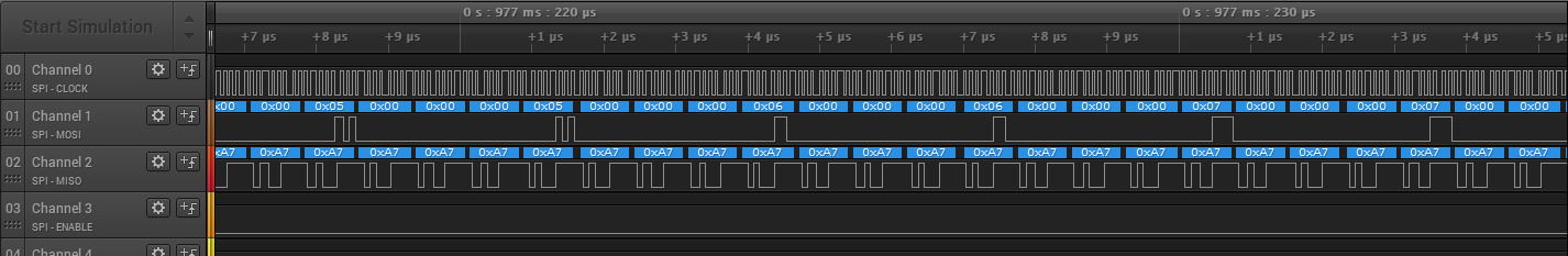
  • checked SPI transmission (reception) of received buffer from LoRa chip, using Logic Analyzer on BOARD B -> corrupted bytes of packet observed (on SPI MISO line)
  • BOARD A and BOARD B functionalities replaced vice versa -> same problem observed
  • SPI master chips used: tested with STM32F417 as well as Nordic NRF52820 -> same problem observed using both of the chips

LoRa configuration used:

#define RADIO_SPREADING_FACTOR LORA_SF10
#define RADIO_BANDWIDTH LORA_BW_1600
#define RADIO_CODING_RATE LORA_CR_4_5
#define RADIO_HEADER_TYPE LORA_PACKET_VARIABLE_LENGTH
#define RADIO_PREAMBLE_LENGTH 12
#define RADIO_POWER_MODE USE_DCDC
#define RADIO_TX_POWER 13
#define RADIO_RX_TIMEOUT 0xFFFF
#define RADIO_BROADCAST_FREQUENCY 2450000000UL

Example of the problem captured on BOARD B: Expected value of bytes: 0x06 and 0x07 but received different values


I have captured the same problem when board A is transmitting bytes of values only 0xFF but board B receives different values, but I was allowed to post only one picture (forum restriction).

When spreading factor is decreased to SF6 the problem with corrupted received packets was not observed so far. What could be the problem around having SF10 as spreading factor?
We tested SF11 and SF12 values as well, didn’t help.

Thank You,
BR,
Lubo

Dear Lubo,
As a fellow developer may I ask the correlated logic analyser view of the sender?
Could you include module setup? i.e. all exhancges from cold boot to first packet exchange.
I’ll gladly help with more info.
Cheers

Hello,
I don’t have exact correlated logic analyser view of the sender from the day that I captured the receiver one. But I’m sending at least recent capture of the sender.
As you can see from it, the SPI clock frequency is different now. We have tested different SPI clock freqs as well, to check whether there should be a problem, but didn’t help.

This is module setup of the sender:

Set standby (XOSC):
80 01
Set reg. mode (LDO):
96 00
Buffer base address:
8f 00 00
TX params:
8e 1f e0
Read register:
19 08 91 00 00
Write register:
18 08 91 ff
Set packet type (LORA):
8a 01
Set modul. params:
8b a0 0a 01
Set packet params:
8c 0c 00 53 20 40 00 00
Set RF frequency:
86 bc 76 27
Set DIO IRQ params:
8d 40 03 40 03 00 00 00 00
Clear IRQ status:
97 ff ff

Send payload:

Write buffer:
1a 00 [data]
Clear IRQ status:
97 ff ff
Set TX:
83 02 ff ff

Thank You,
Lubo

Ok, i’ve read your trace and your description.
I’m not sure about the payload length being set correctly with a Set Packet Params
As a sample check list, i’m doing, these actions in order for both sender and receiver and it’s quite effective for me.

Sender:

  • set packet type
  • set modulation params
  • set packet params (variable length)
  • set nuffer address
  • clr irq
  • set dio irq
  • set regulator mode
  • set tx params
  • write buffer
  • set packet params (with payload length to tx)
  • set tx
  • wait until sent (or simple delay to ensure no race)

Receiver:

  • set packet type
  • set modulation params
  • set packet params (variable length)
  • set nuffer address
  • clr irq
  • set dio irq
  • set regulator mode
  • set rx

Hope it helps.
I’m not having a trace with frames detail. Tell me if that’s necessary…
Cheers,

Detailed set packet params command setting:

8c 0c 00 53 20 40 00 00

8c command: RADIO_SET_PACKETPARAMS
0c preamble length: 12
00 header type: Lora packet variable length
53 payload length: 83 bytes
20 CRC mode: CRC on
40 invert IQ: normal

i.e. I think I’m setting proper payload length (83 bytes). Receiver receives 83 bytes, but some of them are not correct (last bytes mostly).

Could you please tell me what is your HW configuration? Do you use some of semtech development kits or board that you designed by yourself? Do you use TCXO or XOSC (xtal) as oscillator? We have our custom HW board designed for our purpose.
Using TCXO is performance slightly better (problems observed when packet is longer than 136 bytes) than xtal osc (around 83 bytes).
Do you transfer longer packets (>136 bytes) correctly with the SF10 using your HW?

Thank you,
Lubo

Dead Lubo,

You make a point here, I’ve only tested so far with packet of size 0x60. not yet the full 255 bytes, and so far I’ve only played with SF8. I’ll be sure to test that out and then I’ll come back to you.

However, and as you mentioned, I’ve already experienced packet invalid bytes, especially on the last byte. Not sure the reason though. I was about to deep dive in this problem.

I’m running with both modules DLP-RFS1280 and E28 2G4M12S, I don’t have semtech eval board so far. Both boards are running with a XOSC, and have PCB antennas. But according to the SX1280 datasheet, the XTAL PPM shall not be problematic with our scenarios (although given the number of fail I had with that using FSK modulations in previous projects and chips, I may have to ensure LoRa immunity with XTAL PPM variation)

Hope I’ll come to you soon,
Cheers,

Dear Lubo,
I’ve just tested with a SF10 800kHz 4/5 round trip, with frames of 255 bytes. And it does not have any error.
I’m currently testing with 2 E28 2G4M12S modules (you can buy them for ~5$ each on aliexpress).

My setup does as follows:
1/ master sends a frame with a seeded incremental value
2/ slave receives the frame and checks its integrity
3/ slave sends a reply frame with another seeded incremental value
4/ master receives the frame and checks its integrity

Here is the capture of the scenario (the first sending is the master) (https://file.io/GhF0pyCwT6hJ)
Cheers

Hello,

decreasing BW to 800 kHz didn’t help. May I ask what is your preamble length configuration and what is your integrity check solution?
Do you check integrity with the Lora packet status bytes? Or you have additional checksum calculation transfered withing custom data?
As I have written in the first post, in my case, packet status CRC bit doesn’t reflect the error when the data transfer is corrupted.

Thank You
Lubo

Dear Lubo,
At start of traces, there is the detailed configuration for the SX1280, however, here’s a more readable list:

// (ALWAYS FIRST) packet type
SX128xCMD_SET_PACKETTYPE, PACKET_TYPE_LORA,
SX128xCMD_SET_MODULATIONPARAMS, LORA_SF10, LORA_BW_0800, LORA_CR_4_5,
//                             Preamble 8 symbols
SX128xCMD_SET_PACKETPARAMS, 0x08, LORA_PACKET_VARIABLE_LENGTH, 0xFF, LORA_CRC_ON, LORA_IQ_NORMAL, 0x00, 0x00,
SX128xCMD_SET_BUFFERBASEADDRESS, 0, 0,
// clear ALL irq status
SX128xCMD_CLR_IRQSTATUS, 0xFF,0xFF,
// interrupt mapped on DIO1
SX128xCMD_SET_DIOIRQ, 0xFF, 0xFF, // IRQ ALL
                       0,SX128x_IRQ_RX_DONE|SX128x_IRQ_HEADER_ERROR, // DIO1 = RX_DONE+HDR error for LoRa workaround 
                       0,0,
                       0,0,
// set regulator mode (DC/DC+LDO)
SX128xCMD_SET_REGULATORMODE, 1,
//                         13dBm (0x1F)
//                               ramp time = 2us
SX128xCMD_SET_TXPARAMS, 0x1F, 0x00,

I started this morning, and replied you after 100 frames have been sent and received. Now more than 27k have been exchanged, without error.

I do have a checksum for a small part, and effectively, I’m not checking the frame CRC status from the SX1280, i’ll add something about that. My frames are filled with seeded value (if you check the saleae trace you would see that), and their value is checked upon reception.

Hope that helps
Cheers

I’m sorry for replying without examining the trace first. I was struggling with opening the .sal file with my Logic software. I later realized that I need to update to version 2. The .sal file is not compatible with version 1 that I use.
So I’ll go through the trace and see whether I find something that could help me.

Thank You for your help so far.

Lubo

Oh, sorry, I’ve not specified the version. Maybe because I’ve already shared traces in a previous post, and mentionned it there :(, my bad.
Anyway, I’ve explicited the conf, so you may find answer.
Also, don’t get puzzled with the fact I SetTxParams before SetTx in my trace, it’s to workaround a context saving bug.
Keep me posted if you need other details.
Cheers,

Hello topaz,
I found in your trace that you read and write register 0x00EF. But I can not find this register neither in SX1280 datasheet nor in source files of library from semtech.
Could you explain what it is for?

Read cmd: 19 00 EF 00 00 00
Write cmd: 18 00 EF 00 AD

You read from this register right before setting sleep (in initialization part) and you write to this register before you send the data to chip (before cmd 1A 00 [data]).
I’m curious whether this is something important or not.
Otherwise my and your setup looks pretty much similar.

Thank you

Dear Lubo,
This register write is to avoid the SetSleep to wipe an internal state and mess up with retrieval of RSSI/SnR value from upcoming received packet. I’ve shared that workaround in another thread.
You can happily live without that for now (I’ve performed transmission without this write for weeks).

It’s worrying that with the same setup you do experience troubles. Most importantly because you used the DC-DC+LDO conf if the config is the same as mine. But therefore you must check that you feature the DC-DC self on the PCB.

Hope it helps
Cheers

HI,
Which code are you using,
I am using a code lorabasicsmodem.(https://github.com/lorabasics/lorabasicsmodem),
I am trying to receive data from the server( DLP-RFS1280 with stm32- NucleoL073),
But not able to receive it,

Can you please help me to fix it,

regards.