Hello,
I’m currently writing a library for the DRF1262T which is the SX1262 radio for STM32F7 chip.
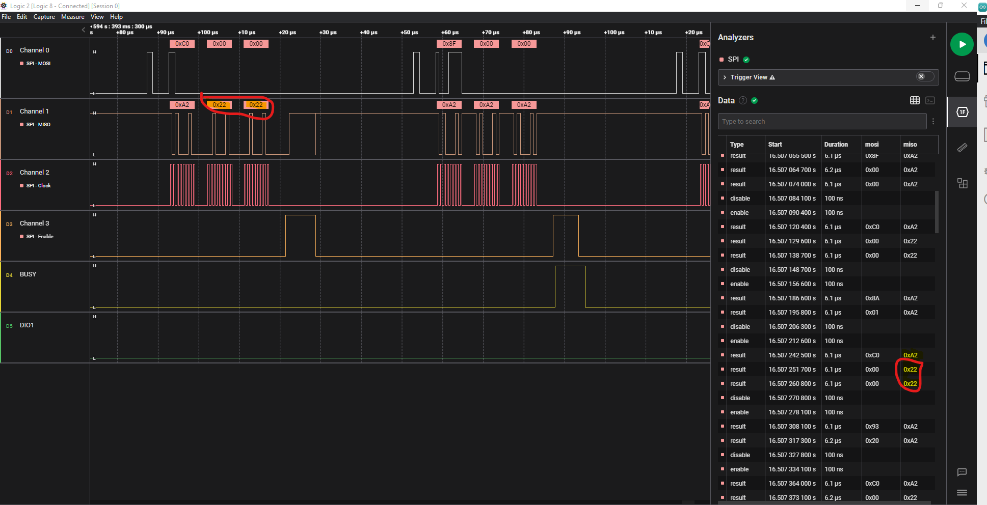
I’m trying to write into and then read into the LoRa Sync Word MSB and LSB registers but I can’t seem to receive the right values.
Also, is 0xA2 feedback normal? I’m always getting that. But in the datasheet there are no status value corresponding to 0xA2.
Here’s my code and here’s what I’m getting on the logic analyzer. I wonder if i missed something.
I started by writing some configuration functions that I put in the main:
HAL_GPIO_WritePin(GPIOA, GPIO_PIN_4, GPIO_PIN_SET);

  SetStandby(hspi1, STDBY_RC);
  SetPacketType(hspi1,PACKET_TYPE_LORA);
  GetPacketType(hspi1);
  SetRfFrequency(hspi1,915.0);
  SetPaConfig(hspi1, PA_DUTY_CYCLE_14DBM, HP_MAX_14DBM);
  SetModulationParams(hspi1, SF9, LORA_BW_125, LORA_CR_4_7, LOW_DATA_RATE_OPTIMIZE_ON);
  //SetPacketParams(hspi1, PREAMBLE_LENGHT_15_8, PREAMBLE_LENGTH_7_0, HEADER_TYPE_VARIABLE, PAYLOAD_LENGTH, CRC_ON, STANDARD_IQ_SETUP);
  WriteRegister(hspi1);
  ReadRegister(hspi1);
Here’s the code implementation details for those functions:
void SetStandby(SPI_HandleTypeDef hspiX, uint8_t StdbyConfig)
{
	while(HAL_GPIO_ReadPin(GPIOF, GPIO_PIN_13) == 1)
	{

	}

	uint16_t SetStandbySize = 2;
	uint8_t SetStandbyCmd[] = {0x80, StdbyConfig};

	HAL_GPIO_WritePin(GPIOA, GPIO_PIN_4, GPIO_PIN_RESET);
	HAL_SPI_Transmit(&hspiX,(uint8_t *)SetStandbyCmd,SetStandbySize,100);
	HAL_GPIO_WritePin(GPIOA, GPIO_PIN_4, GPIO_PIN_SET);


}

void SetPaConfig(SPI_HandleTypeDef hspiX, uint8_t paDutyCycle, uint8_t hpMax)
{

	while(HAL_GPIO_ReadPin(GPIOF, GPIO_PIN_13) == 1)
	{

	}

	uint16_t 	SetPaConfigSize = 5;
	uint8_t 	SetPaConfigCmd[] = {0x95, paDutyCycle, hpMax, 0x00, 0x01};
	uint8_t 	SetPaConfigAnswer[5];

	HAL_GPIO_WritePin(GPIOA, GPIO_PIN_4, GPIO_PIN_RESET);
	HAL_SPI_TransmitReceive(&hspiX,(uint8_t *)SetPaConfigCmd,(uint8_t *)SetPaConfigAnswer,SetPaConfigSize,100);
	HAL_GPIO_WritePin(GPIOA, GPIO_PIN_4, GPIO_PIN_SET);
	//printf("%02x %02x %02x %02x %02x \n\r",SetPaConfigAnswer[0],SetPaConfigAnswer[1],SetPaConfigAnswer[2],SetPaConfigAnswer[3],SetPaConfigAnswer[4]);

}
void SetRxTxFallbackMode();

// Commands to Access the Radio Registers and FIFO Buffer

void WriteRegister(SPI_HandleTypeDef hspiX)
{
	while(HAL_GPIO_ReadPin(GPIOF, GPIO_PIN_13) == 1)
	{

	}

	uint16_t 	SetWriteRegisterSize = 5;
	uint8_t 	WriteRegisterCmd[] = {0x0D, 0x07, 0x40, 0x34, 0x44};
	uint8_t 	WriteRegisterAnswer[5];

	HAL_GPIO_WritePin(GPIOA, GPIO_PIN_4, GPIO_PIN_RESET);
	HAL_SPI_TransmitReceive(&hspiX,(uint8_t *)WriteRegisterCmd,(uint8_t *)WriteRegisterAnswer,SetWriteRegisterSize,100);
	HAL_GPIO_WritePin(GPIOA, GPIO_PIN_4, GPIO_PIN_SET);

}

void ReadRegister(SPI_HandleTypeDef hspiX){

	while(HAL_GPIO_ReadPin(GPIOF, GPIO_PIN_13) == 1)
	{

	}
	uint16_t 	ReadRegSize = 6;
	uint8_t 	ReadRegCmd[] = {0x1D, 0x07, 0x40, NOP, NOP, NOP};
	uint8_t 	ReadRegAnswer[6];

	// SEND COMMAND
	HAL_GPIO_WritePin(GPIOA, GPIO_PIN_4, GPIO_PIN_RESET);
	HAL_SPI_TransmitReceive(&hspiX,(uint8_t *)ReadRegCmd,(uint8_t *) ReadRegAnswer, ReadRegSize,100);
	HAL_GPIO_WritePin(GPIOA, GPIO_PIN_4, GPIO_PIN_SET);
	printf("%02x %02x %02x %02x %02x \n\r",ReadRegAnswer[0],ReadRegAnswer[1],ReadRegAnswer[2],ReadRegAnswer[3],ReadRegAnswer[4],ReadRegAnswer[5]);
}


// Commands Controlling the RF and Packets Settings

void SetRfFrequency(SPI_HandleTypeDef hspiX, float RF_frequency)
{
	while(HAL_GPIO_ReadPin(GPIOF, GPIO_PIN_13) == 1)
	{

	}

	uint32_t 	freq = (RF_frequency * pow(2,RADIOLIB_SX126X_DIV_EXPONENT)) / RADIOLIB_SX126X_CRYSTAL_FREQ;

	uint16_t 	SetRfFrequencySize = 5;
	uint8_t 	SetRfFrequencyCmd[] = {0x86, (uint8_t)((freq >> 24) & 0xFF), (uint8_t)((freq >> 16) & 0xFF), (uint8_t)((freq >> 8) & 0xFF), (uint8_t)(freq & 0xFF)};

	HAL_GPIO_WritePin(GPIOA, GPIO_PIN_4, GPIO_PIN_RESET);
	HAL_SPI_Transmit(&hspiX,(uint8_t *)SetRfFrequencyCmd,SetRfFrequencySize,100);
	HAL_GPIO_WritePin(GPIOA, GPIO_PIN_4, GPIO_PIN_SET);

}

void SetPacketType(SPI_HandleTypeDef hspiX, uint8_t PacketType)
{
	while(HAL_GPIO_ReadPin(GPIOF, GPIO_PIN_13) == 1)
	{

	}


	uint16_t 	SetPacketTypeSize = 2;
	uint8_t 	SetPacketTypeCmd[] = {0x8A, PacketType};

	HAL_GPIO_WritePin(GPIOA, GPIO_PIN_4, GPIO_PIN_RESET);
	HAL_SPI_Transmit(&hspiX,(uint8_t *)SetPacketTypeCmd,SetPacketTypeSize,100);
	HAL_GPIO_WritePin(GPIOA, GPIO_PIN_4, GPIO_PIN_SET);

}
void GetPacketType(SPI_HandleTypeDef hspiX)
{
	while(HAL_GPIO_ReadPin(GPIOF, GPIO_PIN_13) == 1)
	{

	}

	uint16_t 	GetPacketTypeSize = 3;
	uint8_t 	GetPacketTypeCmd[] = {0x11, 0x00, 0x00};
	uint8_t 	GetPacketTypeAnswer[3];

	// SEND COMMAND
	HAL_GPIO_WritePin(GPIOA, GPIO_PIN_4, GPIO_PIN_RESET);
	HAL_SPI_TransmitReceive(&hspiX,(uint8_t *)GetPacketTypeCmd,(uint8_t *) GetPacketTypeAnswer,GetPacketTypeSize,100);
	HAL_GPIO_WritePin(GPIOA, GPIO_PIN_4, GPIO_PIN_SET);

}

void SetModulationParams(SPI_HandleTypeDef hspiX, uint8_t SpreadingFactor, uint8_t Bandwidth, uint8_t CodingRate, uint8_t LowDataRateOptimization)
{
	while(HAL_GPIO_ReadPin(GPIOF, GPIO_PIN_13) == 1)
	{

	}

	uint16_t 	SetModulationParamsSize = 9;
	uint8_t 	SetModulationParamsCmd[] = {0x8B, SpreadingFactor, Bandwidth, CodingRate, LowDataRateOptimization, NOP, NOP, NOP, NOP};

	HAL_GPIO_WritePin(GPIOA, GPIO_PIN_4, GPIO_PIN_RESET);
	HAL_SPI_Transmit(&hspiX,(uint8_t *)SetModulationParamsCmd,SetModulationParamsSize,100);
	HAL_GPIO_WritePin(GPIOA, GPIO_PIN_4, GPIO_PIN_SET);

}

void SetPacketParams(SPI_HandleTypeDef hspiX, uint8_t PreambleLength15_8, uint8_t PreambleLength7_0, uint8_t HeaderType, uint8_t PayloadLength, uint8_t CRCType, uint8_t InvertIQ)
{
	while(HAL_GPIO_ReadPin(GPIOF, GPIO_PIN_13) == 1)
	{

	}

	uint16_t SetPacketParamsSize = 10;
	uint8_t SetPacketParamsCmd[] = {0x8C, PreambleLength15_8, PreambleLength7_0, HeaderType, PayloadLength, CRCType, InvertIQ, NOP, NOP, NOP};

	HAL_GPIO_WritePin(GPIOA, GPIO_PIN_4, GPIO_PIN_RESET);
	HAL_SPI_Transmit(&hspiX,(uint8_t *)SetPacketParamsCmd,SetPacketParamsSize,100);
	HAL_GPIO_WritePin(GPIOA, GPIO_PIN_4, GPIO_PIN_SET);


}